Products
The "K" series offers further improved scratch resistance, as well as high flame resistance and low dielectric loss tangent.
The "XRM" grade has improved low-temperature impact resistance and chemical resistance and is ideal for the exterior of various electronic devices. Furthermore, we are developing environmentally friendly materials with a focus on post-consumer recycling, contributing not only to high functionality but also to global environmental preservation.
Special features
Technical Datasheet
Advice on using Polycarbonate resin (PC resin)
Molding and drying conditions for Polycarbonate (PC) resin
Polycarbonate (PC) resin is molded by general thermoplastic molding methods (such as injection molding, injection compression molding, extrusion molding, blow molding, and pultrusion molding), and the typical molding method is injection molding. PC resin needs to be dried before molding, because the carbonate bond contained in its polymeric molecular chain hydrolyzes when it is heated together with moisture, causing a reduction in impact strength due to molecular weight reduction, as well as silver streaks and voids in appearance. Specifically, it is recommended to dry PC Resin at 120℃ for more than 4 to 5 hours with hot air, so that the water absorption rate in the pellet will be 0.015 – 0.020% or less.
Comparison between Polycarbonate (PC) resin and other transparent materials
Compared to inorganic glass which is a widely used transparent material, Polycarbonate (PC) resin is inferior in hardness, elastic modulus, heat resistance, and solvent/chemical resistance, etc. but has the advantages of having small specific gravity (low density), easy moldability by injection /extrusion molding, mechanical toughness, and easy coloration, which are unique advantages of resin materials. On the other hand, compared to acrylic resin (PMMA resin) which is a typical transparent resin, PC resin is superior in impact strength, heat resistance, low water absorption rate (an indicator of dimension change due to water absorption), and self-extinguishing properties but inferior in high transparency level, as shown in the table below.
In addition, PC resin may cause yellowing and embrittlement if it is exposed to a light containing ultraviolet (UV) such as sunlight for a long time, because it has a benzene ring in its molecular structure (which absorbs near-UV light). Furthermore, it should be also noted that optical anisotropy may become significant depending on the molding conditions, and a decrease in performance due to hydrolysis may occur if PC resin is used under alkaline or moist heat conditions because of the existence of carbonate bond (-OCOO-) in the polymeric repeating unit structure.
| Resin | Impact strength1) (J/m) |
DTUL2) (°C) |
Water absorption3) (%) |
|---|---|---|---|
| PC resin | 640~960 | 121~132 | 0.15 |
| PMMA resin | 11~21 | 68~100 | 0.1~0.4 |
1) IZOD impact strength, ASTM D256A (1/8 inch, notched)
2) DTUL: Deflection temperature under load, ASTM D648 (1.82MPa)
3) Water absorption: ASTM D570 (24 hr, 1/8 inch)
Source: Plastic Pocket Book, 2003 revised version, Kogyo Chosakai Publishing Co., Ltd.
Points which should be considered when injection-molding Polycarbonate (PC) resin
The basic concepts of respective condition elements for injection-molding Polycarbonate (PC) resin are explained as follows:
- Molding temperature: It is generally set to 260 – 320℃. The higher the molding temperature is, the better the flowability of molten resin becomes. As a result, the filling property into a mold (especially the filling property into thin-walled areas) is improved. On the other hand, the molding cycle, that is, the resin retention time in the cylinder, must be considered, and it is also necessary to reduce the retention time as short as possible to minimize the thermal deterioration of the resin.
- Molding pressure: It is recommended to set the injection and holding pressures as low as possible unless sink mark (a phenomenon in which a dent is created due to the shrinkage of resin during cooling) and/or void (a small space in a molded article) occur. However, if the pressures are not high enough, the flowability of molten resin will be insufficient so that it cannot fill a mold. From the perspective of producing high quality molded articles, high molding pressure should be used in order to reduce molding shrinkage (a phenomenon in which a molded article shrinks and becomes smaller than the mold size); on the other hand in order to reduce the strain remaining in a molded article and ensuring good mold release, low molding pressure should be used.
- Injection speed: Higher injection speed increases the flow distance. Therefore, the thinner the product to be molded is, the higher the injection speed needs to be. On the other hand, failures such as flow mark (a trace of resin flow on the molded surface) and burr (a phenomenon in which resin spills thinly into a gap between molds) tend to occur. Through the multistage control of injection speed according to the shape of the molded article, it is necessary to control both the filling property and the appearance of molded surface.
- Mold temperature: The standard mold temperature used when injection-molding PC resin is 70 – 120℃. If the mold temperature is too low, not only insufficient filling and poor appearance such as flow mark but also molding strain (a strain remaining in a molded article. Large molding strain could be a cause of reduction in mechanical strength and optical homogeneity) tend to occur easily. On the other hand, if the mold temperature is too high, the resin tends to adhere tightly to the mold surface, causing poor mold release and deformation after mold release.
Since there are conflicting factors in these molding condition elements explained above, it is desired to devise the shape/dimension of the molded article and to design a mold (Example: flow path design and consideration on molding shrinkage), according to the intended use and performance of the molded article. For more information, please refer to the detailed technical data carried on our web site. In addition, please also inquire about CAE (Computer Aided Engineering) which is widely used in the design of injection-molded articles as a supporting technology for product and mold designs.
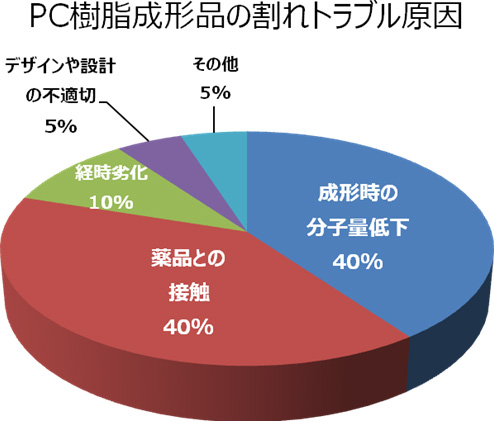
The causes of cracks in Polycarbonate (PC) resin molded articles
The causes of the cracks in Polycarbonate (PC) resin molded articles we have discovered so far are generally classified as follows: Reduction in molecular weight during molding (40 %), contact with chemicals (40 %), time degradation (10 %), inappropriate design (5 %), and others (5 %). The major factors are explained as follows:
- Reduction in molecular weight during molding: Insufficient pre-drying of materials, deterioration due to the retention in the cylinder of a molding machine (including poor selection of molding machine and conditions), and contamination of different kind of resin, etc.
- Contact with chemicals: Chemicals such as oil, grease, printing ink, paint, thinner, alkaline chemicals, etc. Among them, alkaline chemicals, alcohols, and high-temperature phenols break the carbonate linkage of a macromolecular chain which causes a reduction in molecular weight. In addition, aromatic hydrocarbons (such as benzene, toluene, and xylene) and chlorinated hydrocarbons (such as methylene chloride and chloroform) swell or dissolve PC resin.
- Time degradation: Prolonged contact with high-temperature and humid atmosphere and steam, deterioration due to weather, and thermal shock (rapid temperature change), etc.
- Inappropriate design: Concentration of stress in a sharp edge, stress applied to an insert area, and stress applied to a welded area (a joint portion of molten resins from different flow paths where the strength generally decreases), etc.
Influence of and countermeasures against molding strain of Polycarbonate (PC) resin
In general, in the case of injection-molded articles, it is empirically known that residual molding strain is large near a gate (an inlet port through which resin flows from the flow path into the main body of a molded article), at the edge of a molded article, and at areas where wall thickness varies significantly. Since Polycarbonate (PC) resin has relatively poor melt fluidity, attention needs to be paid to these points. In addition, since it is an amorphous resin, cracks could be generated if fats, oils, inks, paints, and solvents such as thinner contact a part of a molded article with large residual strain.
As a means to remove the residual strain of a molded article, it is effective to heat the molded article at a temperature which is approximately lower by 20℃ than the glass transition temperature (hereinafter quote it as “Tg”. Approximately 145℃) of PC resin, keep that temperature for a certain period of time, and then cool it to room temperature. This operation is generally called “annealing process”. The standard is that our PC resin products are annealed at a temperature between 120 and 125℃ for one or two hours.
Although it is considered that molded articles with simple shape and thin wall can be annealed in a short amount of time, there are cases where the ones with complicated shape or thick wall are annealed for two or three hours.
Recycle and reuse of Polycarbonate (PC) resin
Concerning the use of our Polycarbonate (PC) resin product as recycled material, it is recommended to mix new materials with about 20 – 30% of recycled materials. As the percentage of recycled materials increases or as the number of times the materials are recycled increases, a reduction in molecular weight, an increase in the degree of yellowness, and a reduction in the total light transmittance become evident. In addition, in the case of reinforced-grade resins containing a reinforcing material (filler) such as glass fiber, such filler breaks as the resin is recycled repeatedly, leading to a reduction in mechanical strength.
[Explanation] About the characteristics of crystalline and amorphous resins
(1) Macromolecule crystallization
Crystallization of macromolecule (in this document, linear polymer molecule is set forth as a premise for explaining the principle) refers to a phenomenon in which parts of chainlike polymeric molecule gather together to make up flux which are partially arranged in one direction under certain given conditions, for example, under the cooling conditions in the molten state during injection molding or the concentrating conditions in the solution state (Refer to Figure 2), although it refers to a phenomenon in which small molecules and ions are arranged systematically to make up a crystal in the case of molecular crystals (Example: sugar) and ionic crystals (Example: salt) (Refer to Figure 1). In addition, when macromolecules crystalize, amorphous regions with varying molecular conformation other than such crystalline region normally exist together.
blue represents molecules or ions and grey represents crystal lattices (hypothetical concept).
The same crystal lattices continue systematically in the directions of X, Y, and Z axes.
blue represents crystalline regions and grey represents amorphous regions. In the crystalline regions, macromolecular chains form fluxes in the same direction.
In the amorphous regions, macromolecular chains locate indeterminately.
The both crystallizations have a common feature that molecules, ions and polymeric repeating units (monomer units) seek to employ the most stable conformation thermodynamically, using intermolecular forces or ionic binding as driving forces. However, the macromolecule case is essentially different from the ones of low molecular or ionic crystals because of the less freedom of macromolecular mobility than monomers (low molecules) before polymerization; i.e., monomer units are bundled each other within a polymeric chain. This reduction of molecular mobility unique to macromolecules is the cause of remaining amorphous regions. Furthermore, the proportion of crystalline region (“crystallinity”) and the sizes of respective crystalline regions (“crystal size or crystallite size”) are largely dependent on the molding conditions.
Macromolecular chains are basically amorphous when in the molten or solution state, but they crystallize as cooled or concentrated because the effect of intermolecular force (attractive force) becomes evident. However, macromolecules have one more characteristic that their viscosity increases significantly as cooled or concentrated in the molten or solution states, respectively, compared to low molecule systems. Due to this viscosity increase effect, it actually happens that macromolecules become solidified before they crystallize well. Therefore, in general, the crystallinity can be increased by taking a longer time for macromolecular chains to relocate them through slow cooling or slow concentration. It can be understood that so-called amorphous resins such as polycarbonate resin (PC resin) and polyphenylene ether resin (PPE resin) tend to solidify in an amorphous state in the molding process, because they crystallize slowly.
(2) The properties of the crystalline region of macromolecules
Since the crystalline region has a dense structure based on strong intermolecular force, they generally show a higher thermal softening temperature and elastic modulus as well as lower coefficient of linear thermal expansion (CLTE) and water absorption rate (that is, a reduction in dimension change due to temperature and humidity) than those of the amorphous region. Of these, thermal softening temperature roughly corresponds to, in the amorphous region, the glass transition temperature (Tg) which correlates with the rigidity of monomer unit structure (the lowness of mobility or flexibility of molecular structure); but in the crystal region corresponds to the melting point (hereinafter quote as “Tm”) which is higher than Tg.
Therefore, in resin molded articles, the increase of the crystallinity moves above physical properties generally to the preferred direction. However, since the crystalline regions dispersed in the amorphous region function as a stress concentration point induced by external force due to a difference in elastic modulus, the toughness of resin molded articles generally decreases as the crystallinity increases and moves in the direction of embrittlement. If the crystallinity is the same, toughness can be improved by reducing the crystalline size.
(3) The properties of the amorphous regions of macromolecules
The amorphous region in resin molded articles functions as a matrix (continuous phase) containing the crystalline regions (hard and difficult to be thermally-softened) as “fillers” (reinforcing materials to be filled). Although the thermal properties of the amorphous region are dominated by the aforementioned Tg, for the mechanical properties it is important to understand mechanism of the amorphous region exhibiting toughness (durability).
At temperatures lower than Tg, the amorphous region subjected to external force (e.g., tensile, flexural, compressive and torsional stresses, as well as gravity force causing self-weight deformation) causes reversible (elastic) deformation first. This phenomenon is relatively small deformation which can be restored by eliminating the external force, and can also be observed in hard and brittle materials such as inorganic glass. However, the toughness of the amorphous region, in terms of a molecular discussion, depends on how far irreversible (plastic) deformation is allowed after the elastic deformation limit. The nature of the plastic deformation is a process of viscous flow, that is, a process in which macromolecular chains tangled with each other dissipate the energy of external force as heat by moving irreversibly to change their arrangement (conformation) gradually and the entire material deforms while bearing breakage.
A trigger which leads plastic deformation to breakage is occurrence of micro-crack (cleavage) and micro-void. Assuming an ideal amorphous region, that is a case where stress concentration factors such as foreign matter and inhomogeneous structure (e.g., crystalline regions, fluctuation of density in amorphous) do not exist, micro-cracks/voids are considered to be caused by (1) macromolecular chain ends, (2) unbinding of macromolecular chain entanglements, and (3) breakage of macromolecular chains, which could be the cause of very tiny voids in the molecular dimension can be generated in the macroscopic deformation. Among these three factors, (1) and (2) are reduced as the molecular weight increases, because the smaller the number of molecular ends per unit weight becomes and the more difficult the entangled chains become unbound, the larger (the longer) the molecular weight becomes (It can be estimated from an example that the longer the boiled noodles are, the more difficult to unbind the entanglements involved in the entire noodle). That is, larger molecular weight is better for toughness.
Concerning the above (3) Breakage of macromolecular chains which is also associated with the perspective of entanglement as described in the above (2), the hardness of the macromolecular chain (the rigidity of monomer unit structure) is one of the factors. That is, if macromolecular chains are flexible, they can follow the entire deformation without eliminating the molecular entanglements. However, if they are rigid, they cannot follow the deformation due to low mobility and stress is concentrated in the entangled points. As a result, it is considered that breakage of macromolecular chains tends to occur. It can be said that the rigidity of macromolecular chains is the cause of complicated behaviors which contradict each other in a practical way. That is, the higher rigidity increases the elastic modulus of amorphous regions and also increases the aforementioned Tg (increases the thermal softening temperature) but reduces melt flowability (increases the molten viscosity to deteriorate the moldability) as thermal properties. On the other hand, if the molecular weight is decreased to increase the melt flowability, the toughness is reduced as described above.
(4) Crystalline and amorphous resins
Basically, linear polymer molecules have the capability to crystallize under certain cooling or concentration conditions. However, “crystalline resins” generally refer to resins which undergo crystallization so that practically preferred physical property balance is shown under common injection or extrusion molding conditions. On the other hand, “amorphous resins” refer to resins which almost do not crystallize under such common molding conditions.
Engineering plastic materials as “crystalline resin” including Polyamide (PA) resin, Polyacetal (or Polyoxymethylene, POM) resin, Polybutylene terephthalate (PBT) resin, Polyethylene terephthalate (PET) resin, and Polyphenylenesulfide (PPS) resins, etc. are characterized by superior molten flowability and chemical resistance, as well as a profound reinforcing effect (an effect of improving elastic modulus, strength, and heat resistance) by compounding fillers such as glass fiber.
The ones as “amorphous resin” including Polycarbonate (PC) resin, modified Polyphenylene ether (m-PPE) resin, and Polyalylate (PAR) resin, etc. are characterized by transparency, anisotropy, and small molding shrinkage.